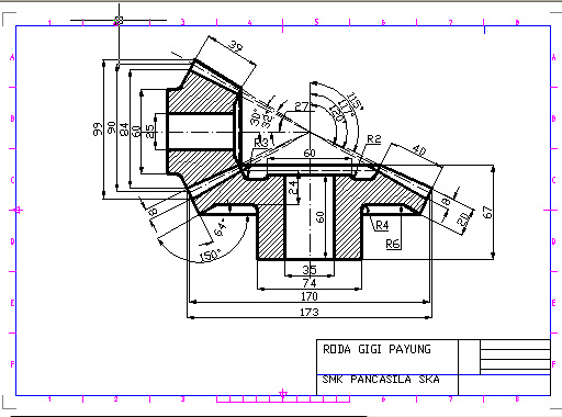
When a machine designer requires a gear when designing a new machine there are two possibilities. A gear drawing is a type of important technical reference required when designing machines. The picture you posted is a little more complicated but because it is an enveloping style worm gear setup but you just need to draw your profile of the gear and a sweep path.
worm gear autocad drawing

Designing the new gear itself and utilizing a standard gear which has already been designed.
Worm gear autocad drawing. In either case the gear drawing is indispensible. Strangely i can draw the worm helix lisp but and the worm gear as a straight tooth ie not at an angle to its the shaft axis but i need to draw the worm gear teeth at an 4 deg angle to ist axis my plan was to revolve one face but it flopped hence the question stephen. A set of worm gears. The worm gear is just a sweep operation.
One way is to get yourself a book that explains the process or look it up on line. The tooth profile will depend on your design but the pitch of your helix needs to match the pitch of your gear. Cadbim library of blocks draw worm gear free cadbim blocks models symbols and details free cad and bim blocks library content for autocad autocad lt revit inventor fusion 360 and other 2d and 3d cad applications by autodesk. The computer aided design cad files and all associated content posted to this website are created uploaded managed and owned by third party users.
A second option would be to use a custom lisp routine that draws 2d gears input the required data let the routine draw the complete gear take what you need and erase the remainder.


